Samudy Jingchuang Injection Molding (Shenzhen) Co Ltd Chen Tianpeng
Introduction:
Flow marks are a fairly common molding defect in the injection molding industry. Whether it is precision plastic parts or large automotive and home appliance molds, they often trouble us injection molding manufacturers. Because flow marks are a somewhat subjective appearance defect, it is difficult for software to express them directly, and Moldflow analysis results therefore offer no intuitive result to display and predict this injection molding defect. This article therefore introduces cases that solve this challenge through product structure changes combined with Moldflow software.
Case Sharing (1)
1. Case Introduction
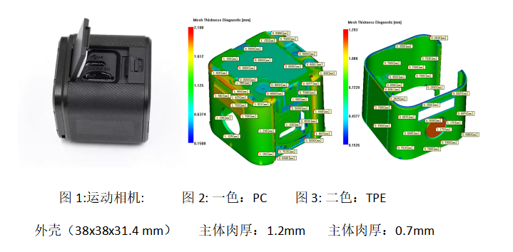
The action camera housing measures 38 x 38 x 31.4 mm (Figure 1). The first shot is PC, with a main wall thickness of 1.2 mm (Figure 2). The second shot is TPE, with a main wall thickness of 0.7 mm (Figure 3).
2. Original Design Plan
The original design plan of this product is shown in Figure 4.
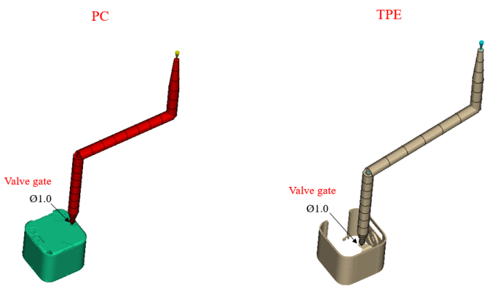
Figure 4: Original design plan
3. Current Problems
First, because the wall thickness of the second shot is relatively thin, and this TPE has poor flowability, the second shot must be filled using a relatively high injection speed (Figures 5-7).
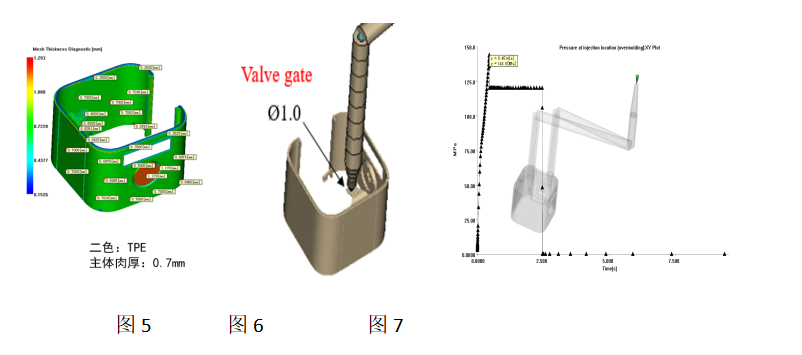

Second, thin walls, high speed, and a gate close to the side-wall appearance bring appearance problems (flow marks). In this case, because the product has thin walls and the injection pressure is already very high, it is impossible to move the gate away from the appearance side-wall area. However, the customer did not agree to change the overall wall thickness or thicken it; they only agreed to locally modify the wall thickness in the top area. As a result, during machine setup on site, low speed could not fill the product completely, and high speed produced flow marks that could not be tuned to perfection (Figure 8).
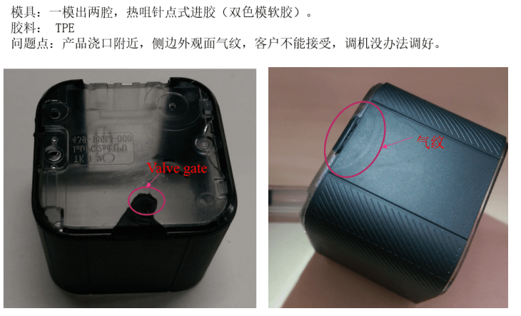
Figure 8
4. Cause Analysis and Improvement Plan
Flow marks are often caused by excessive fill speed, excessive temperature, trapped gas, and so on. Based on the Moldflow fill analysis in this case, since the flow mark location is close to the gate, the preliminary analysis is that the flow marks were caused by high speed and excessive shear temperature (Figure 9).
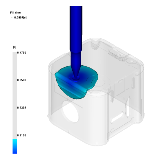
Figure 9
Analysis of possible causes of flow marks: from the product structure (Figure 10), there is a bevel at this location, it is close to the gate, and the wall thickness is uneven. When the melt passes through this area at high speed, the shear heat rises sharply and gas is generated. Guided by the bevel, the melt then strikes the mold surface at an angle in the direction of the red arrow (Figure 11), easily tumbling and forming flow marks. Therefore, the structure at this location is very likely the main cause of the flow marks.
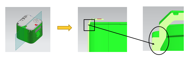
Figure 10: 3D cross-section of the product at the flow mark location
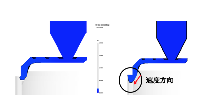
Figure 11: Possible causes of flow marks
As shown in Figure 12, due to the bevel, which is very close to the gate, the melt flows at high speed and, by inertia, strikes the mold side wall at an angle along the arrow direction, leading to flow marks.
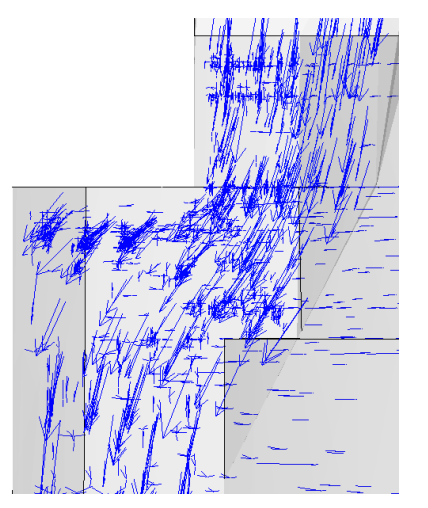
Figure 12: Velocity direction before modification
Therefore, to eliminate flow marks, reduce shear heat, and change the direction of the melt velocity, the melt must be prevented from striking the steel at an angle. To this end, the bevel was removed, the wall thickness was made more uniform, and a gate bump was added at the injection location to make the wall thickness more uniform.
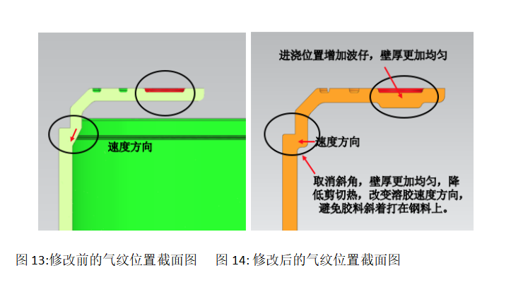
As shown in Figures 15-16, after removing the bevel, the melt direction becomes more consistent. The melt generates a centripetal force at the R corner and, under this force, fills along the surface of the first-shot product, reducing the possibility of shear and tumbling, thereby improving the surface quality of the product.
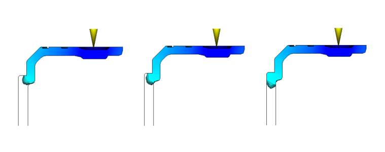
Figure 15: MF flow condition after modification
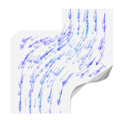
Figure 16: Enlarged partial view
Comparison of the actual improvement effect of the product (Figures 17-18)
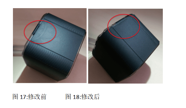
4. Project Summary
Flow marks near the gate commonly occur in thin-wall products with relatively high pressure. The main causes include excessive shear rate, poor venting, and of course structural issues. The success of this case means we can consider such surface issues in the design stage in the future, reducing molding defects caused by structural problems. This is already a great gain for us. In the past, similar finished products had high improvement costs (about CNY 200,000) and long improvement time (3 months). Using Moldflow to analyze the gate location and size before mold manufacturing, we optimized a more reasonable structure and effectively solved the appearance flow mark defect. Not only was the improvement cost reduced to CNY 50,000 (including quality upgrades), but the improvement time was also greatly shortened to 10 days (same as above), along with improved quality.
Analysis of Moldflow's Long-Term Benefits in the Company
1. Project Cost
Using Moldflow can shorten the project cycle by 1-3 months. Each project can save RMB 100,000, with an average of 20 projects per year. Project cost savings: 100,000 x 20 = RMB 2,000,000
2. Mold Cost
Using Moldflow saves an average of 1-2 mold trials. Each mold saves RMB 10,000, with an average of 50 molds analyzed per year. Mold cost savings: 10,000 x 50 = RMB 500,000
Total: 200 + 50 = RMB 2.5 million/year
Experience Sharing
1. Experience Sharing (1): Accurately Analyzing the Fill State
To accurately analyze filling with Moldflow, there are three key points: 1. A correct mesh model — the number of mesh elements must not be too small. 2. Correct material parameters — the material information must be accurate. 3. Reference actual process parameters.
5.2 Experience Sharing (2): How to Correctly Set a Reasonable Injection Time
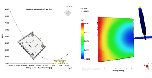
Using DOE in Moldflow: 1. You can find the injection time that yields the minimum injection pressure. 2. You can also set the melt front temperature range to determine a suitable fill speed.
Looking Ahead
The development of the injection molding industry increasingly relies on Moldflow — it is recognition from customers and also the need of the company. Increasingly fierce competition and ever-higher quality requirements demand that we rack our brains and use Moldflow in the right way to create value for the company. In the future, the company will move toward higher quality goals with Moldflow, summarizing and consolidating the prediction, evaluation, and solutions for various injection molding defects. For injection molding problems that currently cannot be directly reflected in Moldflow analysis results, we hope to make incremental progress and get better and better in the future.


 Business Scope
 Component Solutions